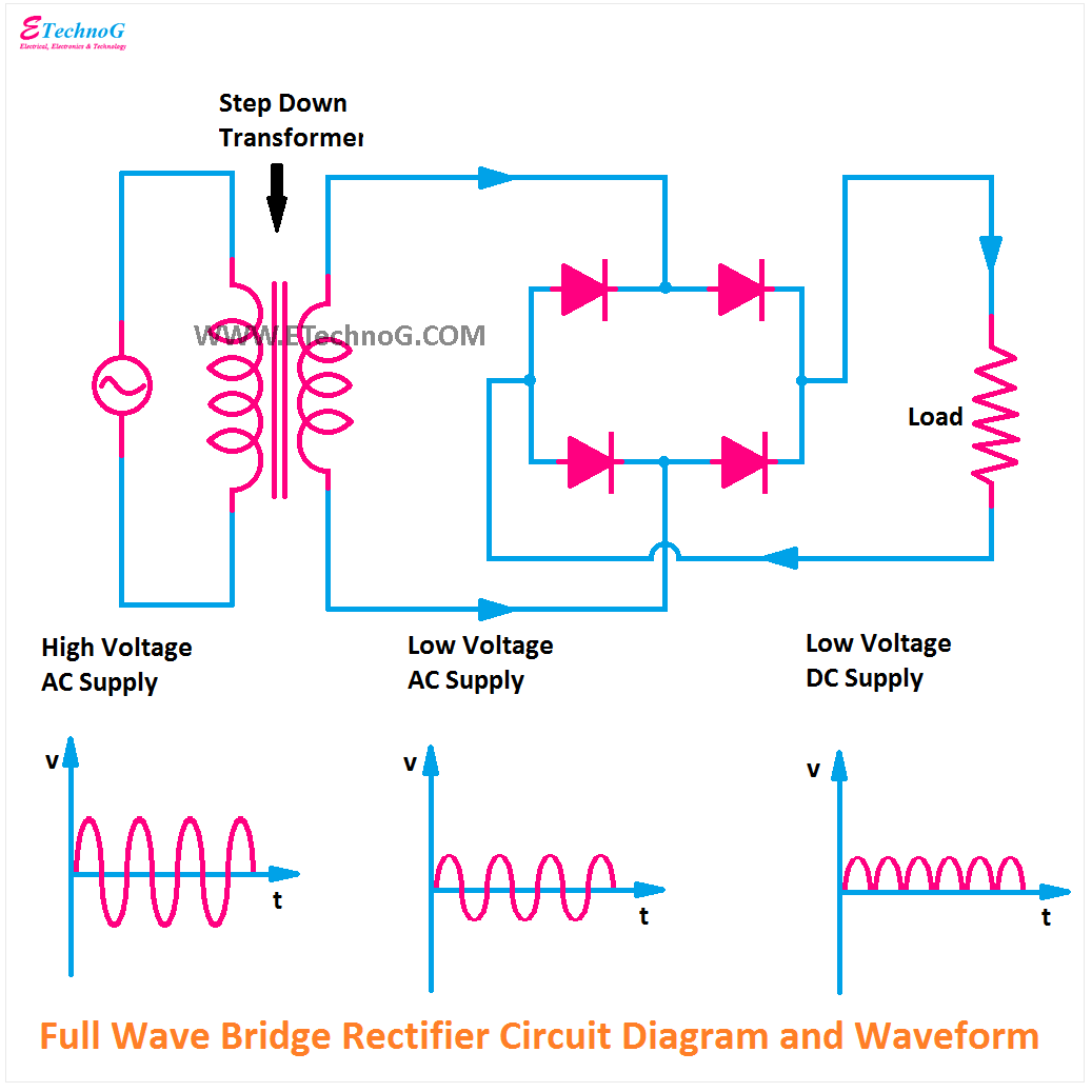
Full wave rectifier graph Rectifier circuit diagram Kbpc3510 bridge rectifier wiring diagram
Ac Rectifier Circuit Diagram
Rectifier filter power supply circuit diagram
Supply circuit power 12v dual diagram output circuitdigest using circuits electrical diagrams control led
How to design capacitance value for a given full wave rectifierRectifier transformer tapped output input waveform Rectifier converter circuitDoubler rectifier electronic rectifier circuit diagram.
Circuit diagram of full rectifier10+ 230vac to 24vdc power supply circuit diagram Circuit rectifier diagram doubler electronic seekic supply power24v smps circuit diagram.
![24V 5A Power Supply | Circuit Diagram](https://i2.wp.com/www.circuitdiagram.org/images/24v-5a-power-supply-circuit.gif)
Ac rectifier circuit diagram
24v 5a power supply9v regulated power supply circuit diagram Supply 24v power 5a circuit diagram sponsored links circuitdiagramHow to wire 24v transformer.
Ac to dc converter circuit diagram without transformerRectifier power supply circuit diagram Power rectifier circuit diagramPdf rectifier circuit diagram.
![10+ 230Vac To 24Vdc Power Supply Circuit Diagram | Robhosking Diagram](https://i2.wp.com/www.discovercircuits.com/DAJ-Schematics/24vac-to-24v-DC-Supply.jpg)
Bridge rectifier
Transformerless power supplyZener diode supply power circuit volt regulated rectifier diagram using 12v wiring bridge wave dc schematic ac transformer theorycircuit half Motorcycle rectifier circuit diagramFull wave rectifier schematic.
Rectifier bridgeFull wave bridge rectifier circuit diagram Simple ac to dc converter using bridge rectifierAc rectifier circuit diagram.
![Simple AC to DC converter using bridge rectifier](https://i2.wp.com/www.engineersgarage.com/wp-content/uploads/2019/10/Circuit-Diagram-Simple-AC-DC-converter-using-bridge-rectifier.gif)
Full wave rectification diagram
Welcome to my personal with really pleasure for all visitors..: diy☑ half wave rectifier with zener diode Low-cost and high power submultiple electronic rectifier circuit+12v and -12v dual power supply circuit diagram.
Rectifier capacitor signal waveform circuitglobe resistor robhoskingAc rectifier circuit diagram Circuit power diagram seekic cost low high rectifier electronic supply.
![Ac Rectifier Circuit Diagram](https://i2.wp.com/electronicsreference.com/wp-content/uploads/2021/03/Schematic-diagram-2-1024x395.gif)
![Ac Rectifier Circuit Diagram](https://i2.wp.com/www.electroduino.com/wp-content/uploads/2021/04/Full-Wave-Bridge-Rectifier-–-Circuit-Diagram-and-Working-Principle.jpg)
![Rectifier Circuit Diagram | Half Wave, Full Wave, Bridge - ETechnoG](https://1.bp.blogspot.com/-ph3wPcxTMhg/YO60L9F14dI/AAAAAAAABM0/svLo3j9BnrEtn4_4Ldv94ZgxqVJXvAE7ACLcBGAsYHQ/s1035/Center%2BTap%2BFull%2BWave%2BRectifier%2BCircuit%2BDiagram.png)
![full wave rectification diagram - Wiring Diagram and Schematics](https://i2.wp.com/circuitglobe.com/wp-content/uploads/2015/12/HALF-WAVE-AND-FULL-WAVE-RECTIFIER-FIG-1-compressor.jpg)
![Welcome to my personal with really pleasure for all visitors..: DIY](https://i2.wp.com/bp1.blogger.com/_1m2qIg_NcPw/R8lJUpKwp4I/AAAAAAAAAbA/Ml0tjsnwDI0/s0-d/Rectifier-Power-Supply.jpg)
![Full Wave Bridge Rectifier Circuit Diagram](https://i2.wp.com/www.theorycircuit.com/wp-content/uploads/2018/03/full-wave-bridge-rectifier-circuit-diagram.png)
![How to design capacitance value for a given full wave rectifier](https://i2.wp.com/i.stack.imgur.com/Et55c.png)
![Full Wave Rectifier Schematic](https://1.bp.blogspot.com/-uzWX38U8Hjs/YO60pnoF8UI/AAAAAAAABM8/otQyNJpK8PIUk9vmeOwTroo0cMf9xL06ACLcBGAsYHQ/s16000/Full%2BWave%2BBridge%2BRectifier%2BCircuit%2BDiagram.png)
![☑ Half Wave Rectifier With Zener Diode](https://i2.wp.com/www.theorycircuit.com/wp-content/uploads/2016/03/zener-diode-12-volt-power-supply-circuit.png)